
IoT Device for sound detection
Project's purpose:
The end product will serve as a home automation IoT device. Once it is complete it will be used to detect specific sounds (doorbell ring, etc...) in the house and alert the user over the internet.
Electronics Design Process
Once I have finalized the project's outline and requirements I was able to start the electronics development.I have started immediately the development process by looking for possible components that could be used in my design. During this process I came across lot of datasheets, some of the datasheet names are visible on the Part "hunting" picture below. It is necessary to read through and read correctly the datasheets as this outcome is key to the whole project's success. Checking the components availability is also a necessity at this point. This can cross-out components that are in a long time shortage position and development is not possible with them anymore. I know that Altium Designer has the Live BOM option for this, however I was using KiCAD in this project.I defined modules that are smaller pieces and fit together to build up the whole project. This helps to break down a larger problem into smaller problems. It also helps to define how each module should work and what other modules expect at their inputs. Once I had the modules and knew which components I will be using I've started to draw the schematic. During this process I used LTSpice circuit simulator and mathematical calculations to support the schematic drawing.
SoC (system on chip)
Power concept and power supply
Sound sensing element and signal conditioning (amplifier)
Programming interface
These modules are visible on the "Schematic Drawing" picture below, each module is circled around with a blue border on the schematic. Generally I would use a hierarchical design but in this case I could fit all the components on a single sheet.

Part "hunting"

Circuit simulation

Schematic drawing


Once I finished the schematic drawing I was able to start the layout drawing process. This I consider an engineering art. The prettier an engineer founds the layout may mean it will perform better, of course there are rules to it as well. In this design I placed effort for the following points.
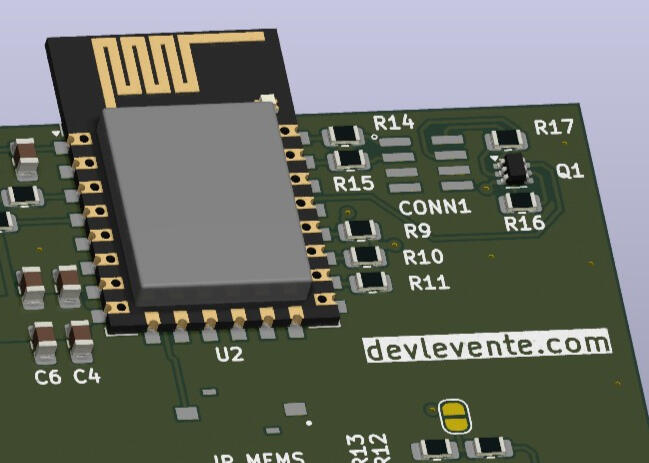
Short distance from MEMS sensor to the AMP input
Decoupling capacitors on the SoC power input
Clear of any metal behind ESP's antenna, placing antenna on the shorter side of the PCB

PCB Layout Drawing

TOP PCB 3D View

BOT PCB 3D View


BOM check and Manufacturing
Before sending the design to manufacturing I have placed the order for the BOM components if they are still available. I was lucky no component went into shortage, I placed the component order. Once all the prerequisite processes were done (schematic, layout, BOM order) I sent my gerber files to the manufacturing company.
Electronics Design Verification
PCBs arrived
BOM Materials arrived
PCBs populated by me
I had everything I needed to verify the design to at least some point. I imagined from the beginning myself in this exact moment and I wanted to support this time by having the ability to separate each modul from the another. On the picture below I've highlighted the jumpers that separates the modules from each other. This helped to isolate early HW bugs and let me fix them faster that having everything connected immediately.

Solder bridges separate modules

On the following pictures below I show my hardware verification. I used my Analog Discovery 2 as a quick and dirty oscilloscope. It's software Waveforms has an awesome feature which let's me immediately listen the audio coming out from the amplifier. I used my PCBite kit which helped a lot in my probing process.

PCBite Hands-free probing

PCBite Hands-free probing


Physical system modelling with C++ and Python
Project's purpose
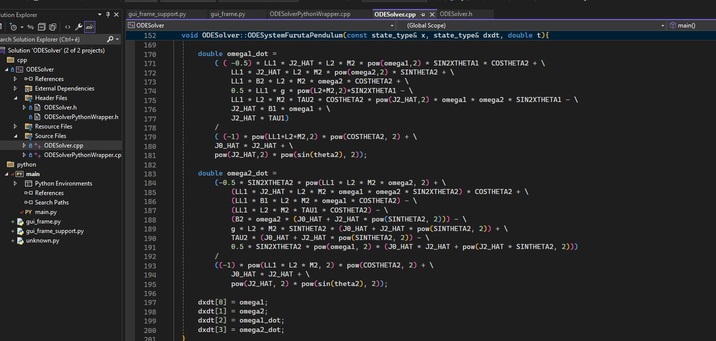
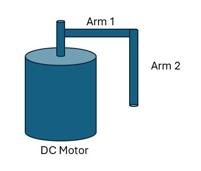
The goal was to model a physical system given by it's motion equations. The physical system is a so called "Furuta Pendulum". I was given the task to write the ODE solver in C++ and then write a Python wrapper around it with a minimalistic Graphical User Interface. My end result was accepted by the project's coordinator.
Furuta pendulum system
I educated myself on the Lagrange mechanics subject with the excellent MIT OpenCourseWare (link). I've used available academic sources and python to derive the motion equations which define the physical system. I was planning to use C++ Boost::Odeint library as this supports solving ordinary differential equations.
Software architecture
The following picture shows the simplified software architecture of the design. The low-level functions written in C++ and these functions are exposed by using the Boost::python library. These compiled into a DLL file (with debug headers).I wrote the GUI application in python and used the TKinter library and PAGE GUI generator tools. I found PAGE a bit buggy but it actually helped me designing the gui
(link to PAGE).

Software structure

Completed application
The software allows the user to set the simulation time parameters (simulation start, simulation end, time-step).The user enters initial conditions for the angels and angular velocities using input fields (θ1,ω1,θ2,ω2). Plotting is started by pressing the "Start plotting" button. The results are shown for the angels (θ1 = top, θ2 = bottom)Even though the time was limited I could spend on this project I learned new concepts and expanded my knowledge.

Finished software

Development environment in VR
I always found VR interesting. Once I have tried Meta's VR experience I became even more interested in learning an experiencing this new technology. I have started my journey by playing with VR games like OhShape. In OhShape the player stands and takes up positions to match the ones that are visible on the upcoming walls, the goal is to fit through the shapes. I then tried Shapr3D software, which let's the user design 3D shapes using the VR headset's hand controllers, even though I have not created detailed object I beleive I could use this to view and "feel" already made objects.What I really liked was the possibility to link my PC to the VR headset and project the PC screen in VR. One can use this to have multiple "portable" virtual screens on it's workdesk. I attach a video I took during my work in VR.